Designing a VGA Graphics Card
January 2022 - Present
I built a functioning graphics card using TTL chips on several breadboards, then designed a custom PCB for it. Based off Ben Eater's video card.
Introduction
This is one of my longer projects, as I've been working on it for almost 2 years now. However, it's also one of my favourite because it combines digital logic design, PCB design, and electronics with being able to visually show off what I've created to people who aren't as knowledgable in electronics.
That last part is quite important to me. Not just because I'm an attention seeker (which you will know that I am if you know me) but also because it easily communicates to people why people do electronics, how it works, and why it's important for our world now.
Chapter 1: Ben Eater Inspiration
Like several of my projects, the inspiration starts with a Ben Eater video. Specifically, his VGA graphics card.
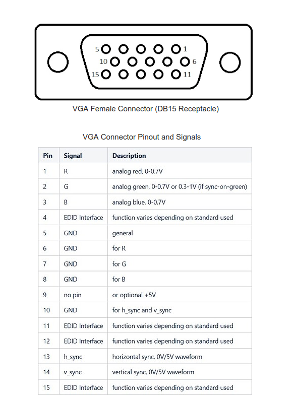
When I first watched this in 2021, I was really surprised just how simple VGA was as a signal format. It's basically just 2 pins for horizontal and vertical sync (which also encodes the dimensions and framerate of the image that is being transmitted), 3 pins for the analog red, green, and blue values that change every pixel, and GND. Of course, I'm ignoring pins that some more advanced VGA cards use to communicate dimensions and other info to and from the monitor, but only the ones I listed before are required. Click here to learn more about the VGA pinout.
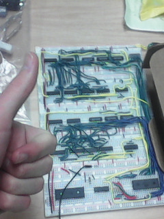
So I asked for Ben Eater's kit for a Christmas that year and I got it! I started building it when I got back to
res that January with some help from my friends (Jet and Kennedy, you guys were great wire strippers).
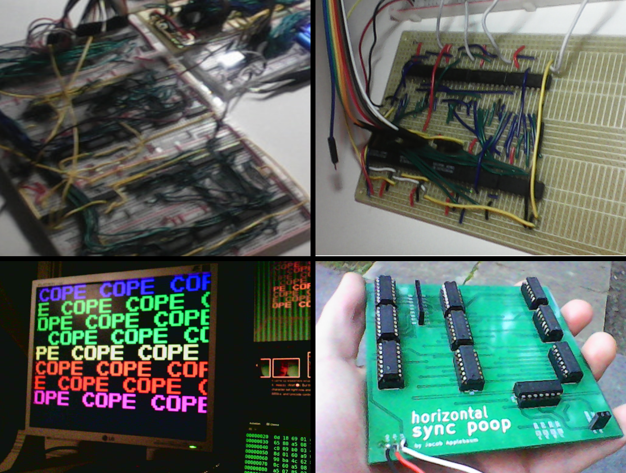
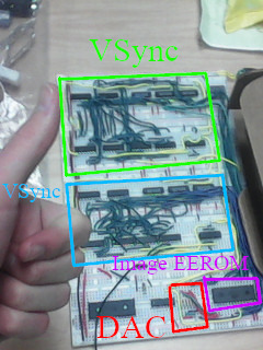
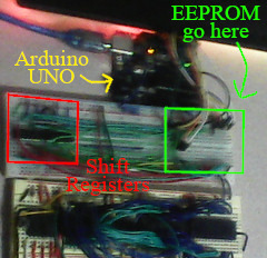
As you'll see above, most of the TTL logic chips on the card (which account for 4 out of the 5 breadboards) are for generating the horizontal and vertical sync signals (HSync and VSync).
These are signals that, when sent to the monitor, communicate frame dimensions in pixels as well as the frame rate. This is amazing to me because it is simply just two square waves with a very specific duty cycle. My guess how the VGA monitor determines this is from a list of possible frame dimension/frame rate combinations that the VGA interface supports and compares front porch/back porch timings.
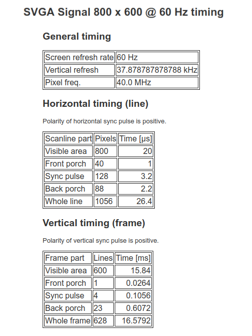
Above, is the signal timing specifics of the frame dimension/frame rate combination that the VGA card uses. This one is used because the pixel clock is a nice multiple of 10 MHz. This is important because Discrete TTL logic chips have a hard time keeping up with signals above 25 MHz, let alone most of the pixel clock rates that VGA supports..
Eater's design gets around this by choosing one that is a multiple of clock rate that TTL chips do support, like 10 MHz. That is why he chose the 800x600 60Hz combination, because it's pixel clock is 40 Mhz. All he had to do was divide each pixel milestone on the horizontal timing by 4. So, the visible area would be 800 / 4 = 200 pixels long. And the front porch would be 128 / 4 = 32 pixels long.
Chapter 2: The Image Converting / Uploading Software
But after I got the actual hardware working, there was still a big hurdle I had to get over... getting pictures on the EEPROM chip. I wasn't about to buy super pricey EEPROM programmer, especially because Ben Eater has literally made a tutorial about how to make your own EEPROM programmer out of an Arduino and 74xx595 shift registers with a github repo with the Arduino code. All I had to do was modify it to set 15 address lines instead of 4, since the VGA card called for a 28C256 EEPROM chip, with 256 Kilobits of memory (32 KB), instead of the 28C16 chip that he was using in the Arduino tutorial, which only had 16 Kilobits (2 KB).
I actually already built this for the 6502 breadboard computer project as you can see here.
Now, this allowed me to upload raw data to the EEPROM as an array of bytes defined in the code of an Arduino sketch, but we still need a way to convert full-on images into raw bytes we can put on the EEPROM. So, I made a python script that converts the pixels from an image into the proper byte representation that would work on the VGA card. The trickest part of that was the color mapping because I had to perform quantization on the full-color images' pixel values into color values that the VGA card supports.
'''
Converts the pixel data in an image (THAT USES THE SPECIAL 332 8-BIT PALETTE) into an array of values that can be copy and pasted into the arduino sketch for programming the EEPROM used for the improved graphics card

By: Jacob Applebaum
Feb 4, 2022
'''
import os
from PIL import Image

count = 0

IMAGEFILE = "jet-64-when" # WITHOUT ".png"

image = Image.open(str(IMAGEFILE + ".png"))
pixels = image.load()

out_file = open(str(IMAGEFILE + ".txt"), "wt")

nums8 = [0, 36, 73, 109, 146, 182, 219, 255]
nums4 = [0, 85, 170, 255]

''' Gets the midpoint between two numbers (1st number should be lower)'''
def midPoint(a, b):
	return int( (b - a) / 2 + a )

''' Gets the closest number in a sorted list from a given number within the list's bounds'''
def getClosest(n, theList, getIndex = True):
	if theList[0] <= n < midPoint(theList[0], theList[1]):
		return int( 0 if getIndex else theList[0] )
	for i in range(1, len(theList)-1):
		if ( midPoint(theList[i-1], theList[i]) <= n < midPoint(theList[i], theList[i+1]) ):
			return int( i if getIndex else theList[i] )
	if ( midPoint(theList[len(theList)-2], theList[len(theList)-1]) <= n <= theList[len(theList)-1] ):
		return int( len(theList)-1 if getIndex else theList[len(theList)-1] )

out_file.write("const byte data[] = { ")
#print("{ ")

for y in range(0, 10):
  for x in range(128):
    try:
      tup = pixels[x, y]
      out_file.write("0b{0:b}".format( (getClosest(tup[0], nums4, getIndex=True) << 4) + (getClosest(tup[1], nums4, getIndex=True) << 2) + ( getClosest(tup[2], nums4, getIndex=True) ) ) )
      print("0b{0:b}".format( (getClosest(tup[0], nums4, getIndex=True) << 4) + (getClosest(tup[1], nums4, getIndex=True) << 2) + ( getClosest(tup[2], nums4, getIndex=True) ) ))
      #print(str((tup[0] << 5) + (tup[1] << 2) + tup[2]))
    except IndexError:
      print("0b0")
      out_file.write("0b0")
      #print("0")
    out_file.write(", ")
    count += 1
    #print(", \n")

out_file.write(" };")
#print(" }")

out_file.close()

os.system(str("xdg-open \"" + IMAGEFILE + ".txt\""))
print(count)
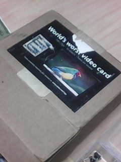
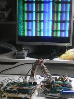
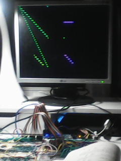
These (below) are all photos that are in-line with the graphical capabilities of the VGA card. This is what 64 colors at 100x64 resolution looks, and you might notice... it's not that bad. And that's because modern image editing software is REALLY good at representing visual information with limited pixels by using various dithering methods.


Chapter 3: The Interface to a Computer
The first two videos in the Ben Eater VGA series basically show how to build a VGA circuit that only reads the static pixel data that was pre-programmed on the EEPROM. But the next two show how to connect it to the 6502 breadboard computer (which is another project/tutorial of his). This was a big deal because it would actually make the graphics card actually usable and programmable.
While yes, there were even more restrictive limitations than the simple VGA card that just read from an EEPROM, this would make interactive graphics programs possible, like games and other visualizations.
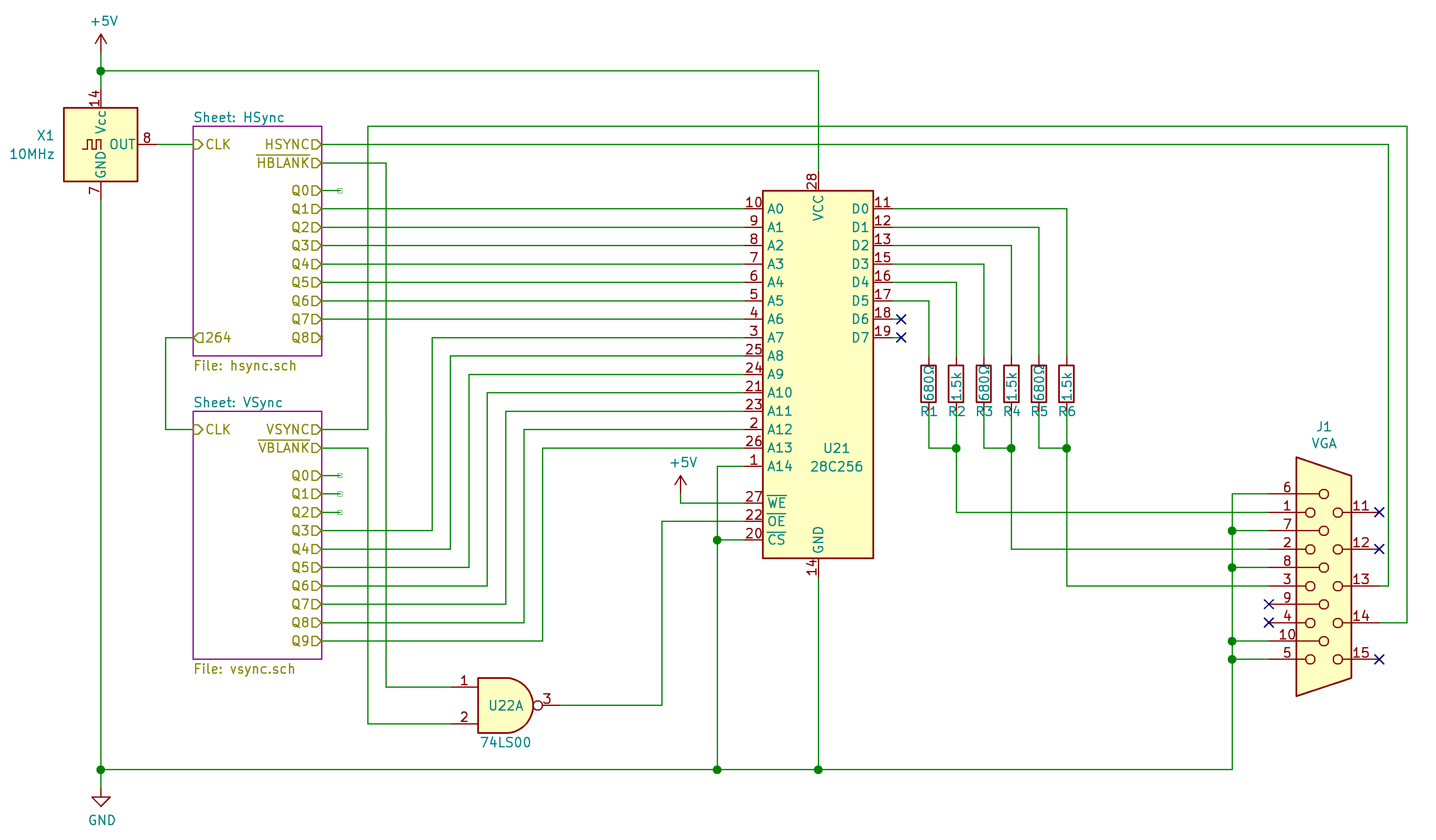
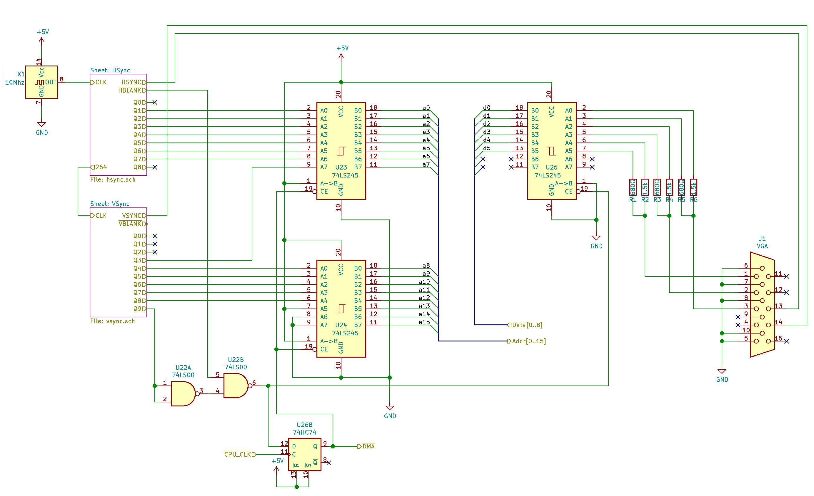
The two images above are the top-level schematic overviews of the VGA card without the 6502 interface and the one with it. The two white boxes near the left are the horizontal and vertical sync signal generators, which account for the vast majority of the TTL logic chips on the card.
Now, about the graphics limitations of the card via this interface, I found it funny how Ben loves to flaunt about how low-spec the graphics card is, even though he is, of course, saying the worst-case scenario of the graphics specs. Particularly, he mentions the hardware is "1 frame per second". This is only true if the CPU spends all of it's time drawing out every pixel on the screen. However, if you're smart about it, and only draw/redraw the pixels you need to each frame, you can get a much higher frame rate. I'm not saying I'm a good enough 6502 assembly language programmer to actually utilize these techniques though.
Chapter 4: The Protoboard
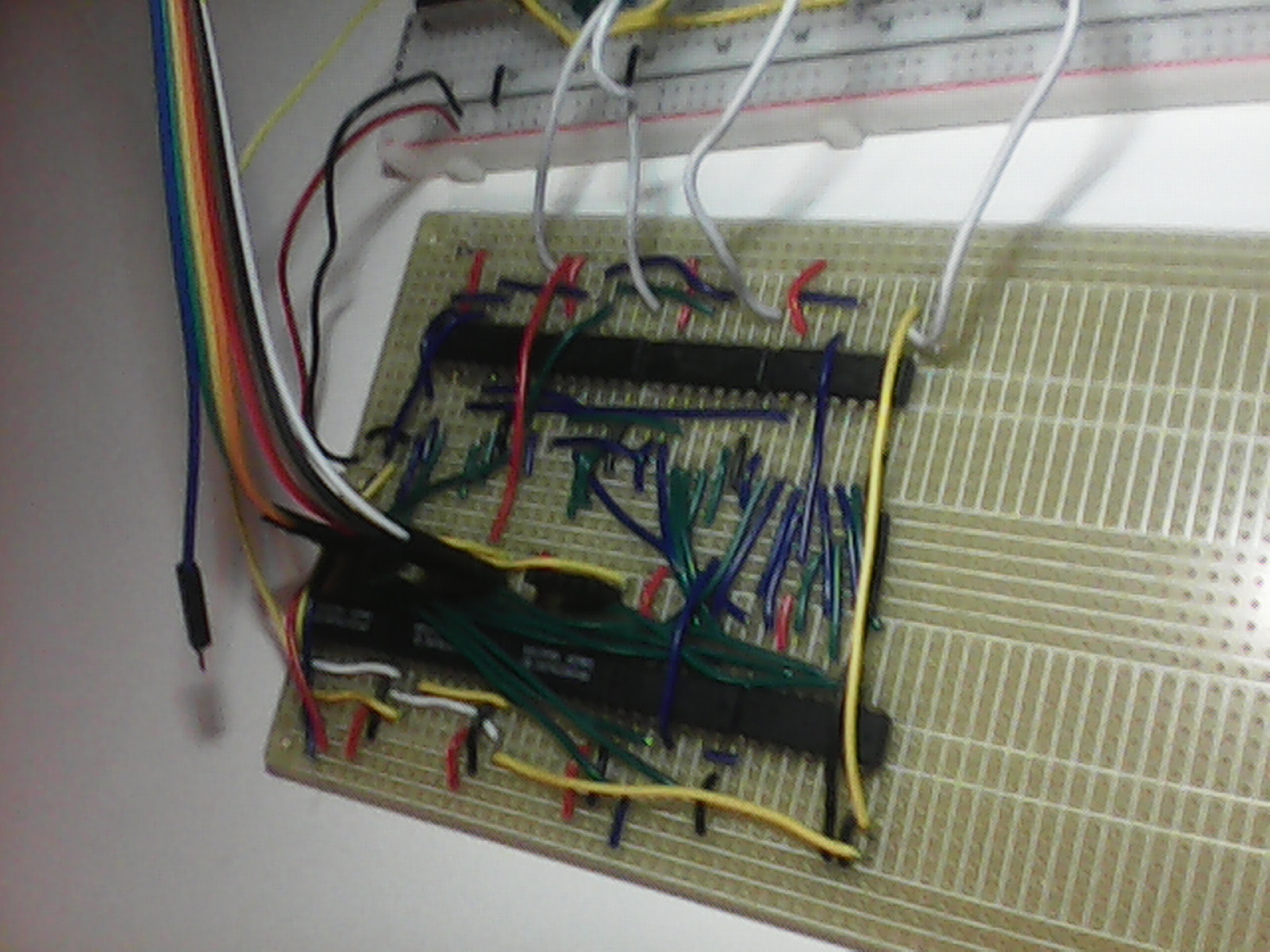
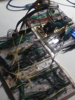
Now, the graphics card was great, I was REALLY happy with graphics card and its implementation thingy. Buuuut, it was taking a LOT of breadboards and every time I transported it, some wires would come out of the breadboard sockets, so I wanted a more permanent implementation of my graphics card.
I didn't really know much about printed circuit board design at the time, so I thought a protoboard would be fun and easy to make, as I don't need to order anything or wait for anything to ship, since I would just go down to my local electronics store (Sayal Electronics in Burlington) and pick up a stripboard (for those not in the know, that's basically a protoboard with many of the holes electrically connected together in lines, akin to a breadboard, but just on a board of copper.
Turns out, manually cutting, stripping, twisting, and soldering almost 100 little wires is time-consuming, who knew. Not to mention, I also had to double or triple check the schematics each time I was about to solder a connection, just so I wouldn't have to do any rework later. Turns out, sometimes I would need to go back anyway because of weak solder joints caused by my cheap soldering iron at the time.
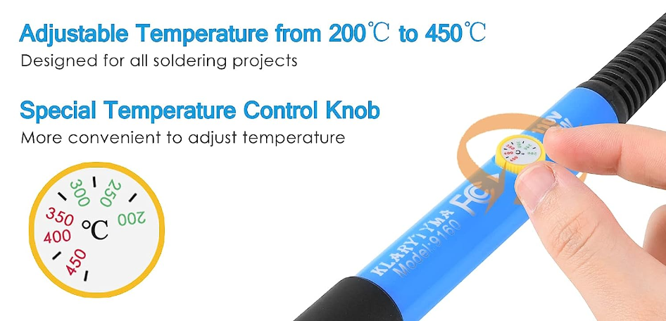
But I mean c'mon, can you really blame me? It was a $30 soldering iron on Amazon that came with a tip cleaner, that weird spiral thingy holder, solder, extra tips, a desoldering pumpg, wire cutters, AND it was temperature controlled (not with an external unit with a display or anything, no, just a shitty little dial on the iron itself).
I'm inclined to say that set me back tens of hours of work in the project, because I would get in my soldering mode once I started soldering, and I wouldn't test anything until I had done a significant enough portion. Then, when I finally did get around to testing, it wouldn't work at all, and I'd have many more places to check for potential issues.
However, once I finally did give up on the protoboard (about 7-8 months after I started soldering it) I dove into a completely different era of the history of electronics manufacturing.
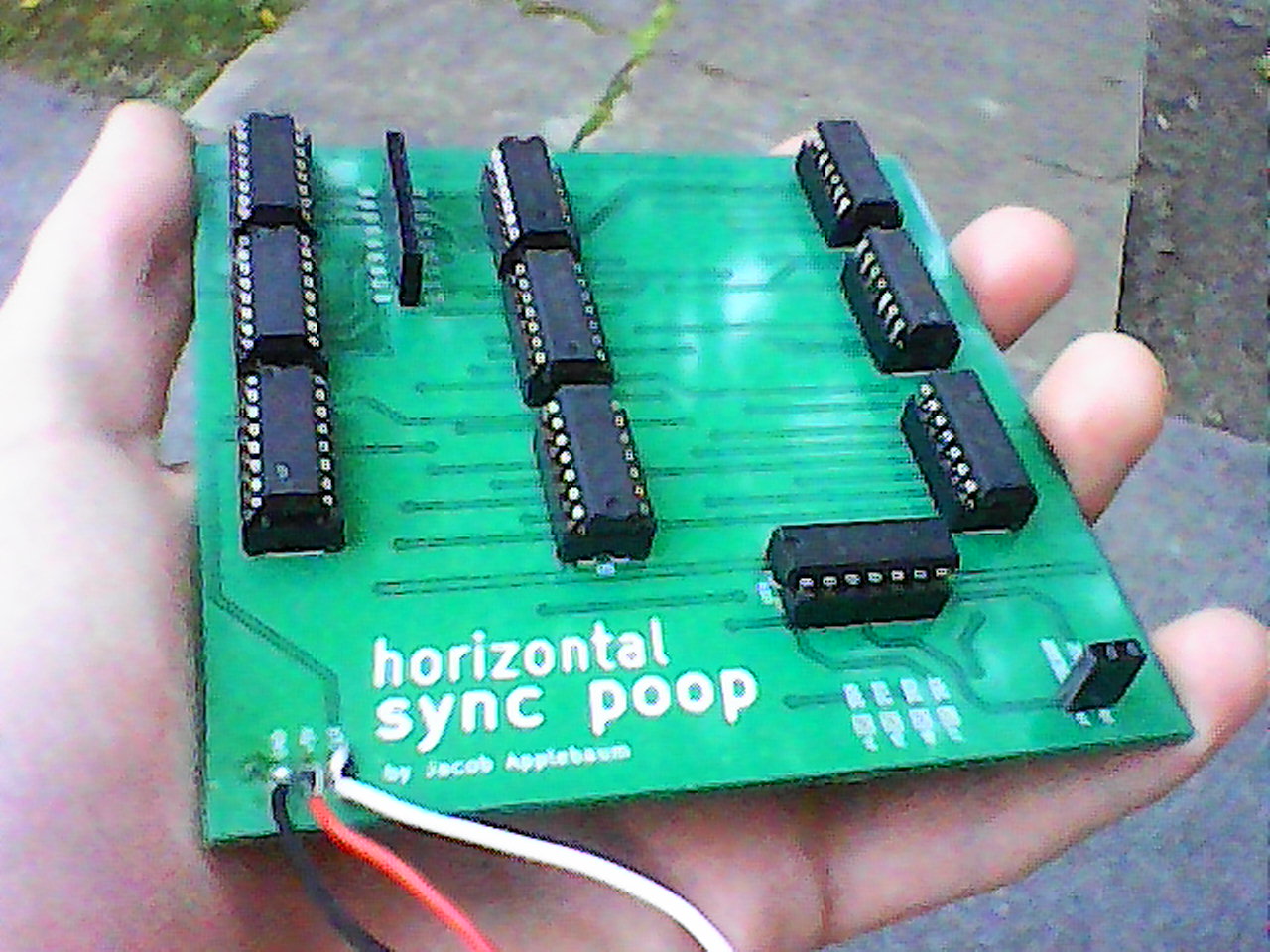
Chapter 5: The Printed Circuit Board
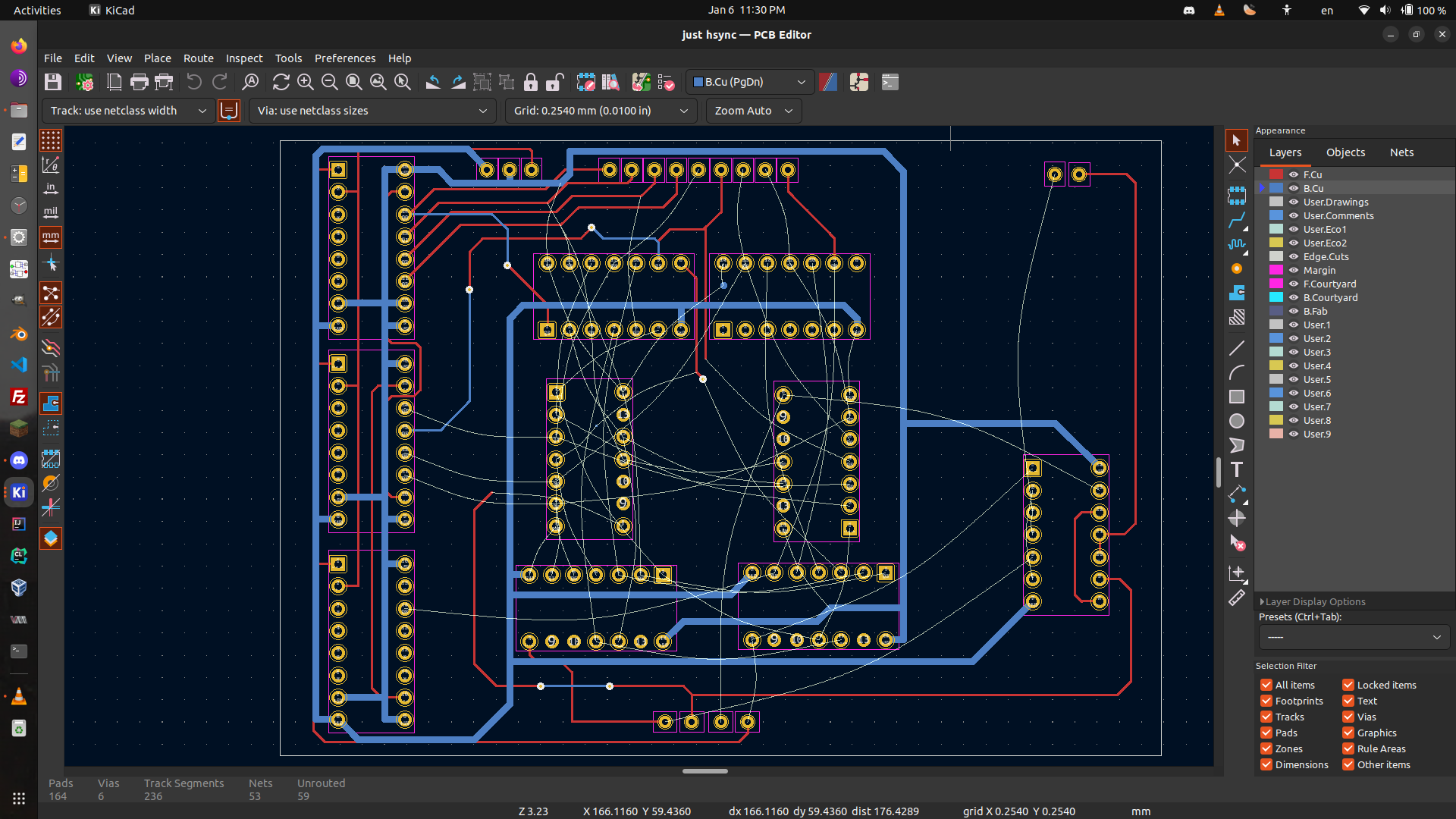
By 2023, I was fed up with the perfboard. I had been working on this project for a year at this point, and troubleshooting my stinky perfboard had taken up 7 months of it.
Chapter 6: The FPGA